
Cartridge Loading
This is a quick study of various phonograph cartridge loading conditions, a rather straightforward analysis using a simple model in Pspice. Obviously, real-life conditions are far more complex, but general trends and first order results can be realized. Effects of RIAA equalization have not been taken into account. The basic schematic is shown below. A cartridge's electrical response is simulated by a voltage source in series with an inductance (Lc) and resistance (Rc). The load capacitance of the interconnect and preamp are lumped together (Ca). Load resistance of preamp is Ra. Moving magnet cartridges have inductances from 100mH to 500mH. Moving coils types range from 5uH to 5mH. Resistance of the windings is proportional to length (number of turns) and wire gauge.
The first thing we notice is that the circuit forms a basic LC resonant tank. Ignoring the effects of the resistances, the resonant frequency is given by:
The larger the inductance, or larger the capacitance, the lower the resonant frequency will be. Indeed, it can easily show up in the audio band, even under common conditions. The following calculator can be used to determine the resonance of your system:
MM Cartridges
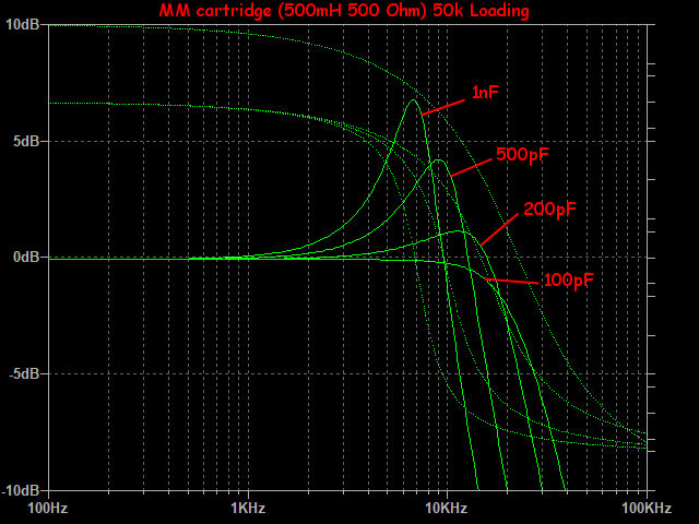
The following plot shows frequencsy response resonance for various loading capacitances. The generic MM cartridge has values of 500mH and 500 ohms, loading is 50k ohms. Resonance in the treble region is seen, with an optimal capacitive loading of about 200pF. Note, this value is likely less than the interconnect cable alone, so additional capacitive loading by phonostage is not a good thing.
Load Resistor Tuning
Ok, given the above analysis, it is pretty easy to calculate the proper load resistance for optimum tuning. It is simply:
Using the previous L and C values:
Now let's do a quick comparison between MM and MC, both using 1nF and 50k loading. Notice the electrical resonance of the MC cartridge (50uH and 5 ohms) is well above the audible spectrum! You won't hear this, although it may be a reasonable thing to tame.
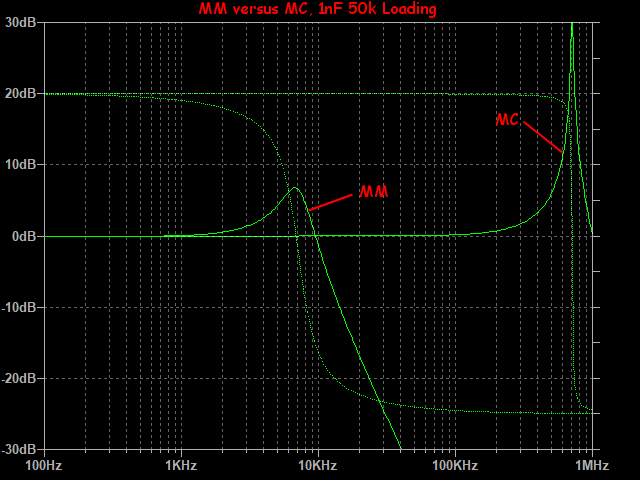
The previous version of this page showed a comparison graph showing the effects of lowering inductance, while loaded by 200pF and 47k. Although correct, my apologies for any confusion caused by implication that all MC cartridges have a self-inductance as high as 5mH.
MC Cartridges
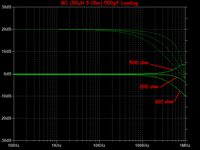
Everything changes with MC cartridges because self-inductance drops to very low levels, anywhere from 5uH to 500uH for a low output type and up to 5mH for high output type. Using a generic low output MC of 50uH and 5 ohms into 500pF loading (solid-state headamp or phonostage) we can see that bandwidth is superb up to the resonance frequency of 1MHz. Load resistance is varied from 100 ohms to 500 ohms. As you can see, there is almost no change in audio band other than a slight attenuation.
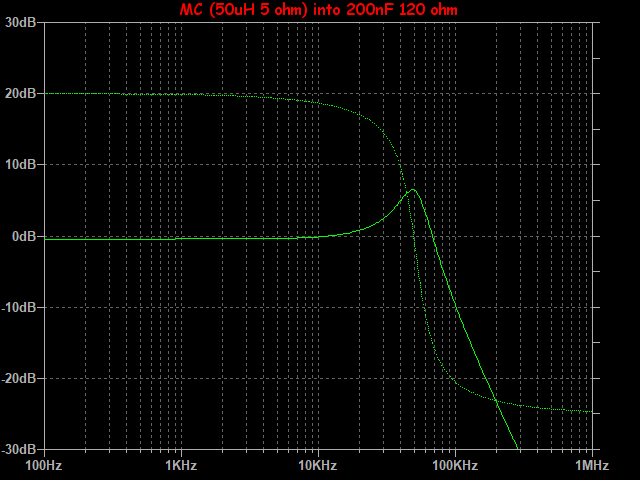
When using a step-up transformer (SUT) with an MC cartridge, things change a bit (refer to section below). Loading capacitance is multiplied as seen from the cartridge's point of view. So a mere 100pF phonostage loading (plus interconnect) reflects a 10nF loading when using a 1:10 SUT. This in turn greatly lowers the resonance frequency. Imagine the effects of 500pF and 47k loading through a 1:20 SUT, where you end up with 200nF and 120 ohms! This response is shown below, but does not include bandwidth rolloff of SUT itself.
Dynamic Braking
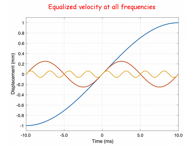
But we all hear what sounds like treble rolloff when using lower resistive loading with MC cartridges! If it is not electrical resonance, then what could it be? My guess is electrical braking. A generator (cartridge) producing output power becomes much more difficult to drive when loaded. This is how AC generators deliver power to your house. The more Megawatts they supply, the more input power (coal) they require to do the job. Hence, the lower the resistive loading, the more effort it takes to move the cantilever. What we get is mechanical damping, and it is proportional to frequency (cartridge output depends on velocity, not amplitude). RIAA equalization was a way to compensate for this, thus correcting for both cutting head and cartridge in one fell swoop, preventing what would have been gigantic modulation in the bass region. As a result, braking force will be much greater at higher frequencies. The braking effect caused by greater coil current (from lower resistive loading) helps to maintain stylus contact with groove walls, lowering both fizziness and noise.
How low can you go? All the way to zero! Transimpedance phonostages (zero ohm input) work just fine. Certainly not with all cartridges, but at least those with low enough inductance. It is good to note in basic physics that a changing magnetic field induces a current in a wire (vector cross product). Same thing for a wire moving within a static magnetic field, which is exactly how an MC cartridge operates. It is by default a current output (generator) device! When unloaded (open circuit), there is a back-EMF (electro motive force) that drives an equal and opposite current, where the result is the output voltage we are accustomed to.
Step-Up Transformers
This is a confusing subject for many because of the nonlinearity of the impedance transformation. Simply put, the impedance differs by the square of the turns ratio. For a 1:10 (20dB) step-up, the imedance is transformed by a factor of 100. That is, with the secondary loaded by 47k ohms, the primary reflects what appears to be 470 ohms to the cartridge.
Standard step-up ratios are 1:5 (14dB), 1:10 (20dB), 1:20 (26dB), and 1:30 (30dB). To find out the loading your cartridge sees, use the following calculator:
Note, these are ideal values that ignore internal series winding resitances of the SUT, both primary and secondary. For a perfect calculation they need to be added in. Additionally, this also means SUT are not noiseless! To understand how much input noise comes from a cartridge and SUT, use the following calculator:
Transimpedance Phonostages
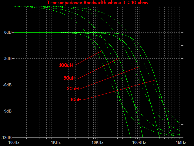
Zero-ohm input phonostages operate an MC cartridge in current mode. In this case, damping is not external, but internal. Bandwidth (-6dB) occurs when the coil's inductive impedance matches it's resistance. At that point, current is halved. This happens at R = 2*pi*f*L. Here is a plot showing frequency response for a cartridge coil of 10 ohms:
To calculate bandwidth of your cartridge in current mode, use this calculator:
Piccolo Zero
The Piccolo Zero is an active transimpedance gain stage meant to replace an SUT. Gain of such a transimpedance stage is given in Ohms (volts per amp), which is also the feedback resistor value. A good starting guess for gain can be made knowing the cartridge's internal resistance (plus resistance of tonearm wiring) and output voltage:
Ideal Cartridge Loading
What is the ideal loading for your system? Well, that depends on a lot of variables, not just cartridge and phonostage, but also speakers, listening room, and how good your hearing is! This analysis was intended to serve as a guide to get you a starting value. From there, listen. Do whatever sounds best.