
LM555 Duty Cycle Modification
Jim Hagerman
04-Apr-2026
First introduced in 1972, the ubiquitous LM555 timer IC has proven to be perhaps the most popular integrated circuit of all time. One notable drawback with the design is that it is not possible to achieve an output duty cycle under 50%. Of course, an output inverter chip could be added, but there is another way! Back in 2018 I came up with a brilliant (in my opinion), simple modification that resolves the problem by adding one additional resistor to the basic astable multivibrator circuit, RC.
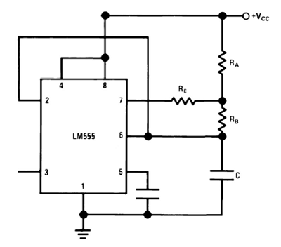
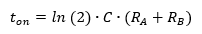
By placing RC in the discharge path, "off" time is increased without affecting "on" time. Note however, if RC is too large then the discharge voltage on pin 6 never reaches the VCC/3 threshold and circuit stops oscillating. The formula for "on" time remains unchanged:
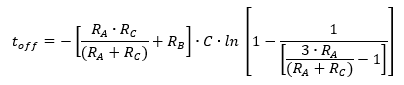
The addition of RC increases "off" time allowing for 50% or less duty cycle. The formula for this is given as:
Note, for this circuit to oscillate Rc must be:

I've created a handy calculator below to determine times, duty cycle, and resultant frequency. It only acts upon a relatively narrow range of operation.